Handheld laser: SUP20S/C Collimator replacement
Jun 08, 2022Be careful:
1. Please pay attention to the site environment during replacement
2. The collimating convex surface faces outward (i.e. the plane after installation faces the direction of optical fiber)
I Disassembly of components
1. Remove the side cover plate and the motor tail terminal
2. Remove the QBH part (there is a Jimmy screw every 120 ° and pull out the QBH after loosening it)
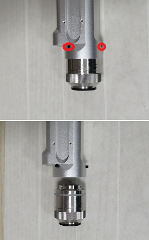
3. Use 2.5 Jimmy screws to remove the connecting screws (as shown in the figure)
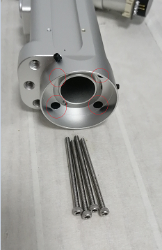
4. Remove the button and disassemble it
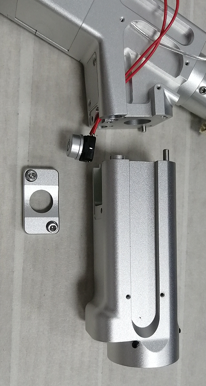
II. Lens replacement
If there is no disassembly tool, use a vernier caliper to remove the locking ring clockwise.
Precautions and placement
1. Locking ring - small ring - collimator - large ring
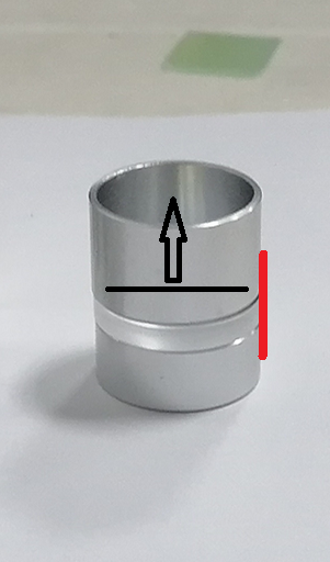
2. The plane of the collimator faces the light facing surface, i.e. upward in figure ③ below
3. Place it as shown in figure ③ during installation, and then take the collimator seat cover
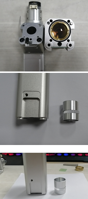
4. If it is not easy to cover from top to bottom, use textured paper to fix the red part in the figure
5. Restore the installation